Assembling a simple racing robot can take a few hours, and the main components of European, American, and Russian robots are roughly the same. You can learn to build such robots in two days at hackathons. If you can’t attend a hackathon and have no one to ask, read our article below. I will explain what we at GoodLancer mean by a simple racing robot. To build this robot, you’ll need basic knowledge of Arduino and electronics.
Design and Assembly Process #
Below, I will outline one approach to designing and assembling a robot. This is not the only way, but it can serve as a starting point.
Let’s define our goals. A racing robot is designed to follow a line (usually a black line on a white background) at the highest possible speed. In our case, the robot navigates using only one type of sensor — optical (usually infrared) line sensors.
The robot follows the black line, trying to keep the track directly under the sensor array at the front of the robot.
Planned Specifications of the Robot #
First, we need to decide on the key components:
- Speed: We typically measure speed as the surface speed of the robot’s wheel in free rotation. For example, if we use a motor with a wheel shaft speed of 1000 RPM and a wheel diameter of 32mm, the wheel’s surface speed will be 1000 RPM * 32 mm * π / 60 = 1675 mm/sec or 1.68 m/sec. The actual speed on the track will be slightly lower than this ideal speed.
- Body Material: 1.5mm thick fiberglass or other thin plastics or corrugated cardboard are suitable for a lightweight body. If you use 5mm plywood or acrylic, the body will be heavy. In most cases, a metal body will also be heavy. Consider all options; you can make a good entry-level robot with a heavy body, but it will require more powerful motors and a larger battery, etc.
- Motors and Power: Lightweight motors with a cross-section of 12 or 16mm are often preferable. This means the robot’s weight should be around 150-200 grams for 12mm motors and up to 350 grams for 16mm motors. The heavier and faster the robot, the more powerful the motors needed. A four-motor setup offers more power than a two-motor setup. Example: build a robot from 2mm fiberglass with breadboards (extra weight) and heavy wheels (metal JSumo), making it about 350 grams. Use Fingertech motors and 3S (11.2V) power since the robot is heavy. Another option: build a robot from 1.5mm fiberglass with a ready-made robot controller and a max speed of 1.5 m/sec. Keep the weight under 130 grams and use 12mm 1000 RPM motors. Power options for most racing robot motors are limited. For 12mm motors, use 2S (7.4V) or 9V with a boost converter. Running these motors at 9V gives more power but shortens their lifespan, so carry spares. For 16mm motors, options include 2S, 9V with a converter, 3S (11.2V), or even 4S (14.8V). The most common power for 12mm motors is a two-cell (2S) lithium-polymer battery, and for 16mm motors, a three-cell battery.
- Microcontroller and Motor Drivers: These must match the motors in voltage and power consumption. Decide whether to use breadboards, soldering, wire wrapping, or terminal connections. The simplest option is robot controllers that combine a microcontroller and motor drivers.
- Sensor Array (Line Sensors): Decide whether to use digital or analog sensors and the total number of sensors.
- Wheels: Important factors are the weight, diameter, and tire material:
- Diameter affects speed (see point 1).
- Weight: Racing robot wheels should be light. Unlike mini-sumo wheels, where surface precision is crucial and weight doesn’t matter much, racing wheels should be light. Thin wheels (GoodLancer, Pololu, Chinese clones) weigh about 4 grams. Fingertech wheels weigh 13 grams, which is acceptable for robots over 150 grams due to their good grip. JSumo wheels weigh 22 grams each and may not be worth it even on a heavy 250-gram robot despite their better grip.
- Tire Material: The simplest way to ensure good grip is silicone tires, including homemade ones. Up to speeds of 1.5 m/sec, simple Pololu wheels or cheaper Chinese clones will work well. Good tires increase motor load and can cause higher currents, damaging motors or drivers.
7. Battery: The battery is one of the heaviest components of the robot and almost the only component that can be placed at the robot’s center of rotation (midway between the wheels) to improve balance. A heavy battery improves balance when centered but also adds load to the motors (weight is weight).
Design and Assembly #
Create the electrical schematic (connect the motors to the drivers, the drivers to the microcontroller, and the microcontroller to the sensor array). If you have a robot controller in the circuit, connect the battery to the power input of the robot controller, the motors to the motor outputs, and the line sensors to the inputs of the robot controller. Don’t forget to power the line sensors from the 5V or 3.3V outputs of the robot controller.
Next, lay out all the components on a sheet of paper to determine how to arrange them, considering the desired width and length of the robot. After this, you can make the robot’s body. If you are using fiberglass, simply cut it with metal shears and drill holes if necessary for mounting the motors, robot controller stands, and sensor array. The battery and electronics can also be attached to the robot’s body with double-sided tape or hot glue. If you are using breadboards instead of soldering and wire wrapping, you can also attach them to the body with screws or double-sided tape.
Programming and Debugging #
After assembling the robot, you can program and test motor control (driving straight or turning), then write a block for reading signals from the line sensors. Most line sensors give a weak signal on white and a strong signal on black. By measuring the difference, you can set white/black thresholds for the sensors, which will depend on the height of the sensors above the line, the track material, and the specifics of the sensor array and sensors.
Once the sensor reading and motor control are programmed, you can create the robot’s core — the PID controller. This part of the program links the robot’s deviation from the black line with motor control. For more details on the PID controller, read our article “PID Controller for a Racing Robot.” – PID Controller for a Racing Robot .
Overall Robot Diagram #
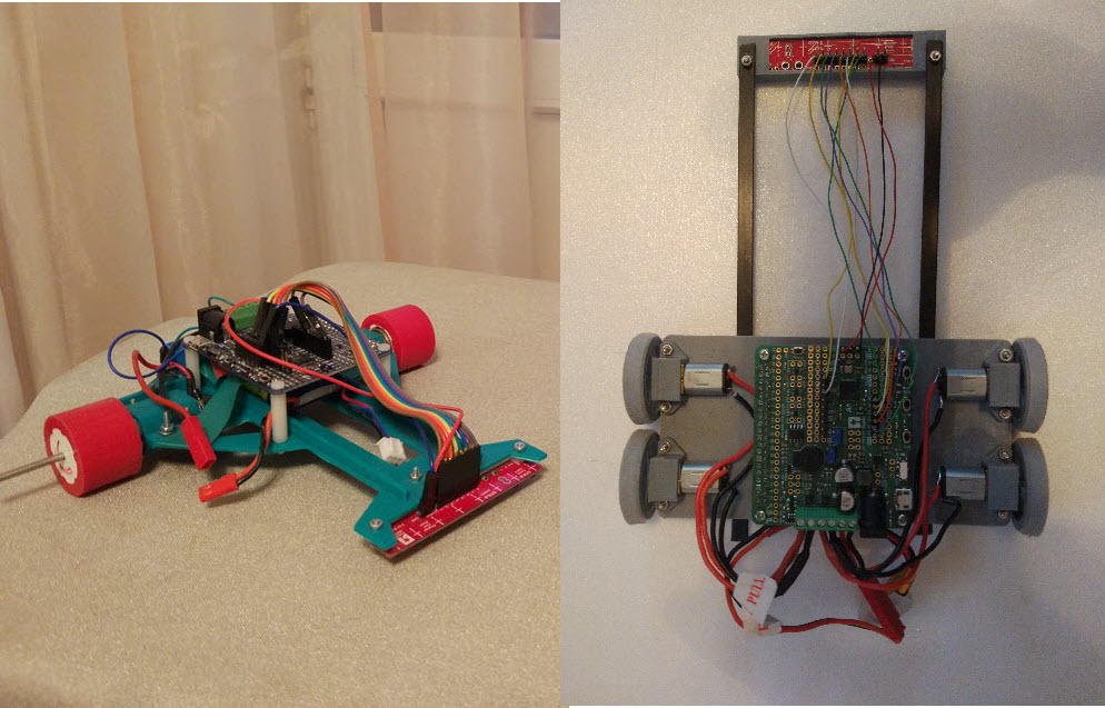
Here you can see examples of simple robots. Let’s look at the parts and components needed to build such a robot. The picture shows two robots: Hermes-3 on the left (green) and Hor on the right. At the front of the robots, you can see line sensor arrays (briefly called sensor arrays).
Racing Robot Body #
The bodies shown in the picture are 3D-printed. Hor’s design additionally uses carbon fiber rods. You can also make a body from fiberglass (cut with metal shears) or even corrugated cardboard, which are also good options. An acrylic body will be too heavy. A normal body weight is 20-40 grams. On simple tracks, a long nose gives an advantage because the robot uses less power for steering. Typical body dimensions are about 15 cm in width and 15 cm in length from the wheel axis to the tip of the nose. According to the rules of most competitions, the maximum allowed dimensions are 25×25 cm or 30×30 cm.
Motors #
In a simple racing robot, gear motors with a reduction gearbox are used to achieve the desired wheel rotation speed. For example, in 12mm (small) gear motors, the motors have a rotation speed of about 30,000 RPM, but the built-in gearbox reduces this to an acceptable level. For instance, a 30:1 gearbox will reduce the wheel shaft speed to a beginner-friendly 1,000 RPM.
Motors are also selected based on the planned weight of the robot. For a medium-sized robot weighing 150-200 grams, two 12mm gear motors with a speed of 1,000 RPM are suitable. Hor and Hermes, shown in the picture above, have slightly different designs. Hermes uses 16mm Fingertech gear motors, providing a good power reserve but slightly affecting the balance. 16mm motors are ideal for fast robots when 12mm motors are not powerful enough, or for heavier robots.
Hor has four 12mm motors with a speed of 2,000 RPM. A four-motor setup offers better traction (comparable to an all-wheel-drive car), but the tires do not operate optimally in turns, as the wheels are angled relative to the robot’s direction of movement. The reason Hor has four motors is its relatively high weight (150 grams) and high speed, with 2,000 RPM gear motors and 35mm diameter wheels.
One of the optimal motor options for a first racing robot is 12mm 30:1 gear motors. Also, don’t forget the motor mounts, as they will be needed too.
Wheels #
Racing robots use wheels with a diameter of 20-40mm with rubber or silicone coverings. Hard tires with deep tractor-like treads are a poor choice due to low grip. Pololu wheels or their Chinese equivalents are good for a first robot. For faster robots, you can use high-grip wheels, but pay attention to the wheel weight, especially for lightweight or four-wheeled robots. Avoid using heavy aluminum or steel JSumo wheels on a 100-gram robot that needs to make sharp turns, as heavy wheels significantly increase the robot’s moment of inertia.
In the picture, Hermes has Fingertech wheels, which allow it to move at high speeds without slipping. Hermes weighs about 250 grams. Hor has much lighter GoodLancer wheels (about 3 grams each) since Hor is lighter, around 150 grams in total, and four 13-gram wheels could negatively affect the robot’s balance.
Battery #
Racing robots use lithium-polymer batteries like those in quadcopters or radio-controlled cars. The main characteristic of such a battery is the voltage, which depends on the number of cells inside. Two-cell batteries (marked as 2S) with a voltage of 7.4V and three-cell batteries (3S) with a voltage of 11.2V are commonly used. The battery voltage should match the acceptable values for the motors and electronics — the microcontroller and motor drivers. A 3S battery can easily burn out a 12mm motor with a nominal voltage of 6V, whereas a Fingertech gear motor works well at voltages of 12V and higher.
Other important battery characteristics are capacity and discharge rate. For first-time robots, batteries with a capacity of 250-450 mAh (milliampere-hours) are typically used.
Sensor Array (Line Sensors) #
The sensor array consists of paired sensors, each combining an LED and a phototransistor. The LED acts as a light source (usually in the infrared range), and the phototransistor detects reflected light. By measuring the reflected light, each pair can determine whether it is over a black line or a white field. If the robot deviates from the line, adjusting the motor current will bring it back on track. A larger number of sensors prevents the robot from wandering; the more it deviates, the greater the difference in motor current, allowing the robot to navigate both gentle and sharp turns.
Racing sensor arrays usually include three to twenty sensors, with 6-8 sensors being most common. There are analog arrays (each sensor gives a signal indicating the darkness of the field under it) and more complex digital arrays. Here’s the difference in usage:
- Analog arrays require analog pins on the microcontroller, while digital arrays require digital pins. Microcontrollers have fewer analog pins than digital ones. For example, a Chinese clone of the Arduino Micro Pro has only four analog inputs and twelve digital inputs. So, if using an Arduino Micro Pro, an 8-sensor analog array can’t be fully used. You would have to connect only four sensors and leave the others unconnected. However, connecting a digital array is straightforward.
- Reading values from analog sensors is simple. In Arduino, you can use the analogRead() function. For reading digital sensor values, it’s better for beginners to use the Pololu library, which is also easy.
- Digital line sensors measure the discharge time of a capacitor through the phototransistor. This theoretically takes more microcontroller resources and time but offers greater accuracy and can read a large number of sensors simultaneously.
Both types of arrays are used in functional robots. Our robots typically use analog arrays.
Microcontrollers, Robot Controllers, and Motor Drivers #
Our robot will be controlled by a microcontroller, but the microcontroller cannot provide a powerful signal to the motors. Therefore, we need an amplifier called a motor driver to control the motors. You can use separate motor drivers and microcontrollers or a combined device known as a robot controller. Robot controllers are usually a bit larger and heavier but include additional useful components on the board, such as buttons, buzzers, and LED lights.
At hackathons and in clubs, separate motor driver and microcontroller boards are often used because they are cheaper. Here, I will describe a slightly simpler but more expensive option using robot controllers. The large blue board on top of Hermes and the large green board on Hor are robot controllers.
Support Balls #
A two-wheeled robot like Hermes can use one or two support balls at the front near the sensor array. Usually, two balls are used to maintain a consistent distance between the sensors and the floor, as this distance affects the sensor readings. As an alternative to balls, you can use plastic standoffs for the boards or even regular screws. In this case, the screw head should be sanded smooth and screwed into the robot body with the head facing down.
The distance at which the sensor array works well can range from a few millimeters to 10 millimeters. The optimal distance depends on the algorithms used and the robot’s design.
Four-wheeled robots usually do not need support balls and can do without them entirely. For example, Hor’s front end is suspended in the air.
Program #
I will expand this section later and explain what each part does. For now, I will just include a sample program code for a racing robot using a P-controller, where “P” stands for “Proportional.” The program calculates the deviation of the black line under the robot from the center of the sensor array and adjusts the motor speeds proportionally to this deviation.
//Test program for a racing robot
//Author - Vyacheslav Nefedov, GoodLancer.com

#include "QTRSensors.h"
#include <AStar32U4.h>
#include <EEPROM.h>

AStar32U4Buzzer buzzer;
AStar32U4ButtonA buttonA;
AStar32U4ButtonB buttonB;
AStar32U4ButtonC buttonC;
AStar32U4Motors motors;

#define DEBUG 0 //1 - Debug mode for outputting sensor values to the serial port

#define KP 70.0 //Speed difference in thousandths per sensor error
#define KD 30.0 //Speed difference in ten-thousandths per change in sensor error per second

const int MAX_PWM = 650; //Average PWM in thousandths of the maximum at zero setpoint
const int MIN_PWM = 650; //Average PWM in thousandths of the maximum at 100% setpoint

const int WHITE = 200; //Sensor signal value on white, determined by testing
const int BLACK = 650; //Sensor signal value on black, determined by testing

unsigned char frontSensors[] = {A5, A4, A3, A2, A1, A0, A6, A7};
#define NUM_SENSORS             8  // Number of sensors used
#define NUM_SAMPLES_PER_SENSOR  2  // Number of readings per sensor. More readings mean fewer errors but longer read time
#define EMITTER_PIN             QTR_NO_EMITTER_PIN  // No control of the sensor array's illumination
QTRSensorsAnalog qtra(frontSensors, NUM_SENSORS, NUM_SAMPLES_PER_SENSOR, EMITTER_PIN);
unsigned int sensorValues[NUM_SENSORS];

int prevErr = 0;
long serialLastT;
float P, D;

int bot_position()
{
  float posSum = 0;
  float posMedian = 0;
  float signal[8];

  qtra.read(sensorValues);

  for (int i = 0; i < 8; i++) {
    // Calculate the darkness level under each sensor
    // 0 - white, 1 - black
    signal[i] = map(sensorValues[i], WHITE, BLACK, 0, 100) / 100.0;
    signal[i] = constrain(signal[i], 0, 1);
    posSum += signal[i];
    posMedian += signal[i] * i * 2;
  }

  posMedian = posMedian / posSum - 7;

  // Print debug messages every 200ms
  if (DEBUG && (millis() - serialLastT > 200)) {
    for (int i = 0; i < 8; i++) {
      Serial.print(sensorValues[i]);
      Serial.print(" ");
    }
    Serial.println("");
    for (int i = 0; i < 8; i++) {
      Serial.print(signal[i]);
      Serial.print(" ");
    }
    Serial.println("");
    serialLastT = millis();
  }

  return posMedian;
}

void move(int leftSpeed, int rightSpeed)
{
  motors.setSpeeds(map(-leftSpeed, 0, 1000, 0, 400), map(-rightSpeed, 0, 1000, 0, 400)); // Set the speed of each motor
}

// Controlled movement, input signal - required turn degree,
// where 0 - go straight, 1000 and -1000 - turn left (right) with the other motor fully stopped
void moveCorrPWM(float correction)
{
  float rightPWM, leftPWM;
  int avgPWM = map(1000 - abs(correction), 0, 1000, MIN_PWM, MAX_PWM);

  float diffPWM = (float)MIN_PWM * correction / 1000;

  leftPWM = avgPWM - diffPWM;
  rightPWM = avgPWM + diffPWM;

  if (0 && DEBUG && millis() - serialLastT > 200)
  {
    Serial.print("correction = "); Serial.print(correction);
    Serial.print(" left PWM = ");
    Serial.print(leftPWM);
    Serial.print(" right PWM = ");
    Serial.println(rightPWM);
    serialLastT = millis();
  }

  if (!DEBUG)
    move(leftPWM, rightPWM);
  else
    move(0, 0);
}

void setup()
{
  Serial.begin(9600);
}

void run()
{
  float correction;
  float err;

  float err_arr[] = {0, 0, 0, 0, 0, 0, 0, 0, 0, 0};
  int err_p = -1;

  serialLastT = millis();
  prevErr = bot_position();

  do
  {
    err = bot_position();
    err_p = (err_p + 1) % 10;
    err_arr[err_p] = err;

    P = err * KP;
    D = (err_arr[err_p] - err_arr[(err_p+11) % 10])*KD;

    correction = P + D;

    // Print debug messages every 100ms when in debug mode
    if (DEBUG && millis() - 100 > serialLastT)
    {
      Serial.print("err=");
      Serial.print(err);
      Serial.print(" P=");
      Serial.print(P);
      Serial.print(" ");
      Serial.print("D=");
      Serial.print(D);
      Serial.print(" ");
      Serial.print("correction=");
      Serial.println(correction);
      serialLastT = millis();
    }

    moveCorrPWM(correction);
    delay(1);
  }
  while (!buttonA.isPressed() && !buttonB.isPressed() && !buttonC.isPressed()); // Stop moving when any button is pressed
  move(0, 0);
  delay(500);
}

void loop()
{
  // Line following - triggered by button A
  if (buttonA.isPressed())
  {
    delay(2000); // Pause for two seconds
    run();
  }

  move(0, 0);
  delay(10);
}


